LibreOffice extension for the graphical notation
This gallery tool for LibreOffice simplifies the process of creating static publication-ready network graphs according to the guidelines proposed in the article “Connectivity concepts in neuronal network modeling” [1]. The living reference of the graphical notation is curated here.
With this extension, users can compose networks by dragging and dropping pre-defined nodes and edges. You can download the extension here:
Installation and settings
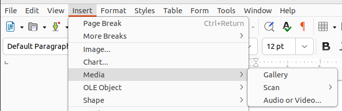
To use the Graphical Notation extension in LibreOffice, download the extension and install it with a double-click. We recommend to use LibreOffice Draw for creating stand-alone figures. Once installed, access the gallery by going to “Insert” - “Media” - “Gallery”. On the right side you can click on the gallery icon () and go to “Graphical Notation”.
How to use
To utilize the various components, drag them onto the workspace. To establish a connection between nodes, drag the desired edge onto the workspace and connect the start and end points to the desired node.
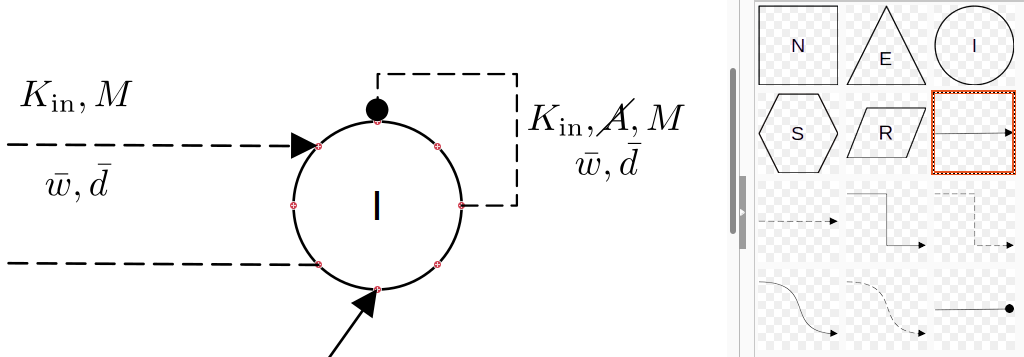
Tip: If you select an object, you can change the color and line thickness under “Properties” (Shortcut: Ctrl+Alt+1).
Annotation
Annotations of edges are best realized with the LibreOffice extension TexMaths. This tool facilitates easy insertion of correct annotations through the following abbreviations defined in NEST’s Connectivity concepts.
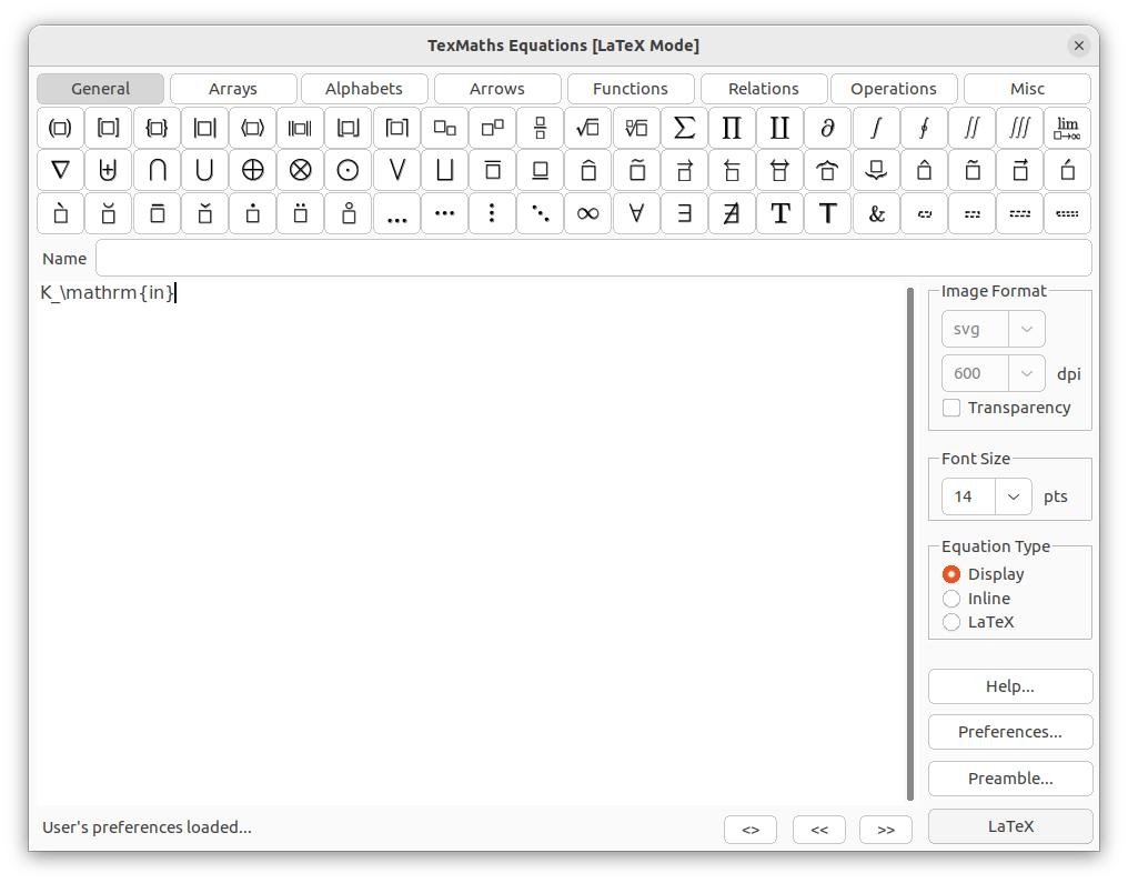
By clicking on “LaTeX” in the bottom right you can add the annotation to the workspace. For “prohibited”, you need to
add \usepackage{cancel} to the preamble in the LaTeX extension. Here are some annotations with the right LaTeX
code based on the graphical notation for the following connection rules:
One-to-one:
\delta
All-to-all:
\Omega
Random, fixed in-degree:
K_\mathrm{in}
Random, fixed out-degree:
K_\mathrm{out}
Random, fixed total number:
K_\mathrm{syn}
Pairwise Bernoulli:
p
Explicit:
X
Prohibited:
\cancel{A}
Constant paramter:
\overline{w}
Distributed paramter:
w $\sim$ D
To edit an annotation, select the annotation to be edited and then click on “LaTeX” in the top right-hand corner. There you have the possibility to edit the code again.
Tip: If you go to the “Arrays” tab, you can simply select the 2x1 array and write the formulas on top of each other.
Save
The best way to save the file is to click on “File” and then on “Export…”, there you can select the desired file type and click on “Export”. We suggest to save in the native text-based .fodg format and export as vector graphics (.eps or .svg) if needed.
Development
If you want to add your own symbols, for example for nodes or edges, you can just hold the symbol which you want to add and drag it into the gallery. You can find more information about it on: https://wiki.documentfoundation.org/The_Gallery_LibreOffice